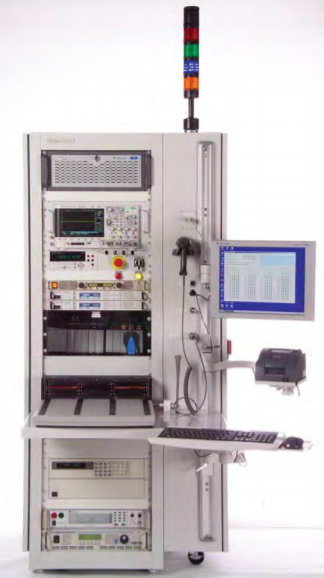
Automated Test Equipment (ATE) Application
Automated Test Equipment
Computer controlled testing has helped to drive manufacturing productivity by increasing efficiency and improving quality. Automated test equipment (ATE) plays a crucial role as it enables more vigorous testing at faster rates and in a more controlled manner than was previously possible using manual procedures. ATE can involve a single measurement made continuously at very high rates or multiple measurements made by a host of different instruments. Measurements made on a device under test (DUT) or unit under test (UUT) are typically calculated, stored and analyzed in an automated fashion by some form of computer. The process helps to remove human error and allows fault diagnosis to be performed in reproducible manner even when sophisticated measurements are involved. Our ATE also offers a complete solution for customer suppliers and subcontractors, integration management, installation, PM (preventive maintenance) and diagnostics in cases of failure and malfunctions.
To allow easy integration into ATE systems Spectrum makes available software and instrumentation drivers that work with 32 bit and 64 bit versions of Windows and Linux. Programming of the cards is possible using a wide range of languages such as LabVIEW, LabWindows/CVI, C++, MatLab, Borland Delphi, Visual Basic, VB.NET, C#, J# and IVI.
Each digitizer card can have from one to sixteen channels and multiple cards can be linked together with Spectrum's StarHub system to create instruments with up to hundreds of fully synchronous channels. This makes them ideally suited to applications where multiple signals or test points are to be monitored. Some cards also offer additional analog and digital I/O capabilities as well as advanced triggering and clock options so that they can work together with a host of different test instruments.
CPU based embedded systems now play an increasing part in the monitoring and control of the mechanical and electrical components in many areas of our technological environment. This artcle shows the realization of a verification tool to help reduce the cost of measuring, optimising and verifying the timing performance of critical real-time embedded systems within the avionics and automotive industries.
Mechanical Measurements Using DigitizersMeasurements on mechanical devices and systems using a modular digitizer requires the use of a variety of transducers or sensors in order to convert mechanical parameters such as force, acceleration, pressure, rotational speed, and their kindred into electrical signals you can measure. This article is a primer on making such measurements using a modular digitizer.
Power Measurements Using Modular DigitizersLine power measurements are commonly required to evaluate the performance of devices or circuits. Modular digitizers can make these power measurements. Digitizers are voltage responding measurement instruments. They can also measure current using suitable current probes or current shunts.
The relative advantage of our solutions is in the integration of a unique platform (management system) that generates QA and QC standardization throughout product lifecycles. This platform combines a range of tools and methods which include:
- Creation of tests and processes without code (suitable for engineers, technicians and content experts) that turn a project into a process and significantly reduce time to market (TTM).
- Management of measuring equipment (T&M), ensuring that equipment replacement does not require the adjustment of tests (code), validation control, self-testing and the tracking of malfunctions
- Centralized or decentralized database (local or cloud-based), including test process logic, test run results and the generation and management of reports in various formats
- Links to engineering information such as schematic diagrams, specifications and procedures, thereby enabling the preservation of knowledge in the system and protection of the customer's IP
- API interface to additional management systems, such as ERP, PLM and CRM.
- Unique tools and algorithms for automated malfunction detection and debugging, integrated in an integrative FRACAS system.
- Application for the local or global management of test system maintenance (TSM).
- BI system for use at all organizational management levels: process managers, product managers and enterprise managers (business management).
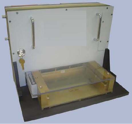
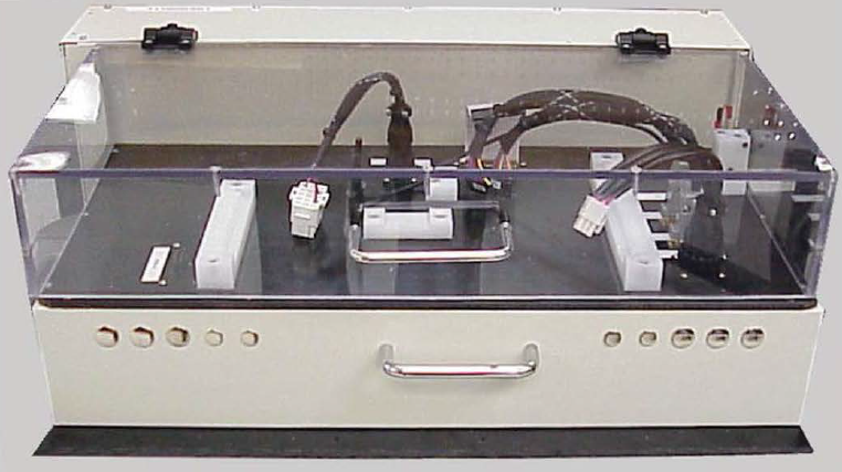
Self-Test Fixture for Functional ATE

Self-Test Fixture with cover open showing: Resister Loads, Relay and Digital IO Controls, Ethernet and USB Test devices.
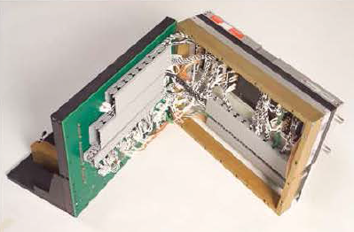
Interface Test Adapter (ITA) For Military Power Supplies
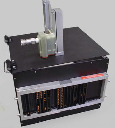
ITA with hookup for Thermal Hood on top Where the UUT is plugged in
Front View of Interface Test Adapter

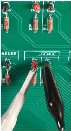
Front View of Interface Test Adapter (ITA) with Cover Removed allow access to test points with clips for Scope and DMM Probe.
Side View Front View of Interface Test Adapter
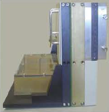

Adapter Open to allow easy access to wiring
Sub Assembly Boards Text Fixture
Application: Sub Assembly Board Test
Feature: Plug In Cable to UUT Multiple Board Type on the same Test Fixture.
Repairing boards is a challenge especially if design data is missing or incomplete. When that happens you can benefit from JTAG devices on the board (PCB Assembly) you’re working on.
See what’s wrong even without design dataBoundary-scan in a JTAG device gives access to its pins. Using the devices’ boundary-scan, JTAG Technologies’ AutoBuzz tool can automatically learn the connections between JTAG devices on a known-good board. A full connectivity compare by AutoBuzz between the results from a faulty board against those learned from a known-good board can then reveal failing devices and connections
Enhanced fault search with design dataIf design data is available the boundary-scan capabilities of the JTAG devices can be used with JTAG Technologies’ Buzz tool to monitor the activity of design signals and to ‘buzz-out’ connections interactively to verify the connectivity between pins. The Clip tool allows you to set-up a sequence of test patterns/vectors making it easy to test non-scan device ‘clusters’.
Checking processor-based boards without using firmwareIn a processor-based design Core Commander helps you to verify the connectivity between the microprocessor or microcontroller and memory and I/O devices at speed. No embedded software / firmware, emulators or debug tools for software are needed.
Re-use tests from design or manufacturingIf you have access to the boundary-scan tests used during the design of the product or used in manufacturing then you can directly (re-)use these tests in service. The ProVision run-time platform or any other run-time environment, eg. LabVIEW, LabWindows, TestStand, C, C++, C#, .NET, Visual Basic, ATEasy, can be used.
Device ProgrammingIn service devices may be re-programmed after repair, or for system upgrades, using readily available programming files. Since any type of device can be present on a board, the complete range of devices and device types are supported by JTAG Technologies service equipment
JTAG Interface HardwareThe single TAP JTAG Live controller or the dual TAP JT 3705/USB controller provide a great low-cost hardware solutions to access the JTAG chains(s) on the board. With an optional JT 2111 DIOS module connector pins can be accessed via boundary-scan.